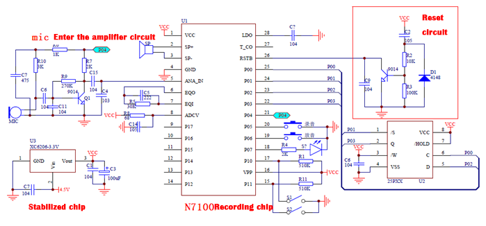

The N9397 recording chip is developed by Jiuxin Electronics, which uses a plug -in SPI memory to achieve the function of recording. Its main feature is that the sound is clear and the recording time is long. The recording time that can be provided is 32 minutes. One of the remarkable features of N9397 is the flexible storage time. Customers choose the corresponding plug -in SPI Flash capacity according to the length of the recording time of their needs. Compared with other recording chips or circuits, N9397 has the advantages of long single -piece recording time, flexible control, low cost, and clear voice.
N9397 has three modes: key control mode, parallel control mode and second -line serial control mode. It is convenient to apply it in various occasions, which is a standardized recording module with high cost performance.

◆ Use the 8 -bit DSP kernel recording chip NR7100S, 16 -bit ADC input, 16 -bit DAC output;
◆ The voice content is stored in the plug -in SPI Flash, and it can be repeatedly wiped more than 100,000 times, and the preservation time is more than 100 years;
◆ The built -in intelligent file system, which does not produce storage fragments;
◆ The recording file is stored in Flash in ADPCM format to save storage space;
◆ Multi -stage recording and sound release operations, each section does not limit the length of time, can be recorded 220 sections;
◆ Support the capacity range of the plug-in SPI-FLASH from 1M Bit to 64M Bit, and the recording can reach more than 1000 seconds;
◆ Support standard keys, one -segment recording mode, parallel mode and second -line serial port mode control method, convenient control;
◆ High sound quality, low noise, long recording distance, built -in AGC gain;
◆ Built -in 0.5W audio amplifier, you can directly drive 0.5W speakers;
◆ Support LINE line recording and MIC live recording;
◆ You can set the sampling rate by yourself, support 6K to 16K sampling;
◆ There is a busy signal output instruction;
◆ The voltage range is DC2.7V to 4.5V, with a low voltage detection circuit;
◆ It can be widely used in the fields of telephone recording, industrial control, fire protection, toys and other fields.
◆ The module uses DIP28 packaging. The main control recording IC is encapsulated by SSOP28, which is small;
◆ Power -saving mode only consumes less than 150UA;

The N9397 control operation mode is a section of the keys, one -to -one mode, standard key mode, and MCU second -line serial control, respectively. Each mode has been fixed before the factory is burned, so users please book the control mode they need before use.
One -piece key recording mode
A period of recording mode includes a recording buttons and a sound keys. Automatically remove the content in the memory before the recording. The recording is low and effective in the level. Press the recording and release the button to stop the recording. There is no time limit for recording, limited to capacity storage time. After the memory is full, it will & rdquo; beep & rdquo; alarm. The sound of the sound is to reduce the sound of the pulse, and the keys is 10ms.

One -to -one record -up mode
One -to -one recording sound includes a recording button and 8 address buttons; P05 is a switch switch of recording pitch. P05 is high -electricity, P10 & mdash; P17 is the 8 -way sound mode. P05 is low -electricity, P10 & mdash; P17 is the 8 -way recording mode. The recording button is low level operation, low -level recording, stopping the recording at high levels, and a warning after the memory is full. The sound of the sound is low -level loop, and the high level stops the sound. There is no time limit for each recording, limited to capacity storage time. The keys is 10ms.

Standard button mode
The standard button operation mode includes a recording key, a current paragraph voice playback key, a next key, a previous button, a volume adjustment key, and a eradication key. The recording button is operated on/off, click the recording, then press the stop recording, and then press a period of voice to cycle. Can record 220 paragraphs, each recording has no long time limit, limited to capacity storage time. After the memory is full, it will & rdquo; beep & rdquo; alarm. The number of recording segments will also & rdquo; beep & rdquo; alarm.
Pressing the current paragraph of the current paragraph will play the current recording content. The next and the previous songs are controlled separately. The volume adjustment of the keys to regulate the volume, circulate the volume, and adjust the volume of 4 levels. The erase of the cutting key is pressed as the current recording content erase, and long press to erase all the contents of the entire memory.
MCU second -line serial port mode
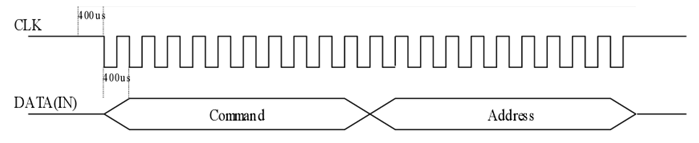
The main control MCU of the second -line serial port operation mode is controlled by two communication cables, which are clock CLK, data data., The communication port and the time sequence are as follows.
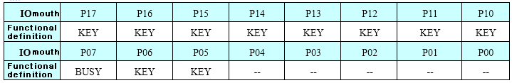
Port distribution

MCU second -line serial timing chart
Before the data is sent, the CLK signal is pulled down 400US to wake up the chip in advance, and then the CLK starts to send. The data is set to the CLK ascending position. The data starts from the low position. Each CLK is greater than 800US and less than 5ms. Data, the first 8bit is the command Command code, and the latter 8 is the address code ADDR code.